Networking – The basics

Network Types

LAN– A Local area network, as its name implies, is a geographically limited network usually restricted to a building. No third party service providers are involved in these networks.

Main characteristics:

  1. Limited to a geographic area
  2. Most of the time less expensive(less network equipment involved)
  3. High transfer speeds

WAN-A wide area network is what connects LANs.  It’s not restricted to any particular geographic region and may even operate in opposite parts of the world. There are many third party vendors in this area, Common broadband internet service providers and MPLS vendors fall under this category.

Main characteristics:

  1. Not limited to any particular geographic area
  2. Interconnection of multiple LANS
  3. More expensive (network equipment costs)
  4. More complex, harder to deploy and implement
  5. More error prone (due to the transfer distances involved)

Network Topology(physical structure)

Common, modern network topologies

  • Bus topology – In a bus topology a single cable is used to connect all the workstations in a linear way. The signals are broadcasted to all nodes, but the stations only process the frames addressed to them.

  • Ring topology – a ring topology is a network were every node is connected to exactly 2 other nodes to form a unidirectional pathway that forms a circle or ring. Signals are sent from node to node in this topology.

  • Star topology – here, each node is individually cabled/connected to a central point (hub, router, switch, server, etc.) which functions as a multi-port repeater. Signals from a station are broadcasted to all of the devices on the hub. This is the simplest and most common network topology. Popular due to the fact that a single cable failure wouldn’t affect the whole network like in a bus topology. One of the major downsides is that it requires more cabling than a bus topology.

  • Hybrid Topology-is when 2 or more different network topologies are connected.  Examples are star-ring and star-bus (or tree topology), tree topology being one of the most common network setups in this day and age.

Network transmission methods

Data packets can be transmitted in the following 3 ways:

  • Unicast: the destination address is encoded into the packet by the source, then sent to the network and subsequently delivered to the appropriate address.

  • Multicast: the packet is encoded with a multicast address by the sender, the packet is sent to the network and a copy of the packet is delivered to each single destination within the multicast address.

  • Broadcast: the packet is encoded with the broadcast address and sent to the network where it’s delivered to every node on the network.

Networking Hardware

LAN Hardware

In a network, there are 2 components, the nodes or devices and the links or cabling interconnecting them. There are various devices with different roles that all come together to form a network. These devices are:

  • Switches: Switches serve to connect together all the LAN connections. They are able to redirect and filter information to/from destination addresses.

  • Hubs: think of it as a much more basic switch, in that it can only run at half-duplex, cannot distinguish packets and deliver based on addresses, but instead merely transmits to every node attached.

  • Repeaters: They serve to regenerate and send signals from one repeater to another. They do not modify data in any way, their function is to help extend the range of networks by boosting weak signals.

  • Bridges: Bridges are like repeaters, but they can also discern destination addresses which enable it to deliver to specific destinations.

  • Routers: Routers are one of the more advanced components in a network, able to perform various network functions, but their most essential is the ability to route and filter information into different networks.

WAN Hardware

WANs involve expensive and complex network equipment capable of providing robust signals to service large areas. Modems are devices that are commonly used to process these long-range signals (usually in analog form), turn them into digital, and connect the LAN to the WAN. MPLS (Multiprotocol Layer switching) networks have emerged as the predominant WAN networks used in businesses for almost a decade now, due to their resiliency and flexibility.

  • Modems: These act as a gateway for the LAN into the WAN. They establish a connection with the service provider and translate high-speed analog transmission technologies like DSL (digital subscriber line) and satellite connections into digital signals that can be used by more common network equipment like routers, switches, and computers.

  • MPLS network: MPLS is a high-performance technique for sending data from one network node to another. By multiprotocol, it means that it supports various level 2 network access technologies like ATM, DSL, cable (coaxial), fiber and satellite.

Communications Technologies

There are 2 widely adopted protocols for communications, the wired one being known as Ethernet, and the wireless equivalent being ieee802.11.

  • Wi-Fi:  Wireless LAN communication technologies using the 802.11 specification (the wireless LAN equivalent of Ethernet) exist under the brand name “Wi-Fi”, mainly using the 2.4 and 5 GHz spectrum for wireless transmissions. The latest standard, 802.11ac, offers speeds of up to 1gigabit by taking advantages of the 5 GHz spectrum.

  • Ethernet: By-far the most widely employed LAN (and increasingly, WAN) technology due to its inexpensiveness, ease-of-use and overall universal adoption in countless devices and adapters. Ethernet is a link-layer protocol from the TCP/IP suite, defining how data is sent and transmitted. Ethernet and its various iterations are discerned by their naming scheme, where each subsequent generation increases the speed 10-fold (i.e. 10 mbps, 100mbps and gigabit Ethernet).

Network Cabling Technologies

The physical Cables and connectors influence design, capabilities and capacity. Some utilize electrons to transmit data(copper wire), others use photons(fiber).

  • UTP: Unshielded twisted-pair is an industry-standard along with fiber, UTP cables are made up of 4 distinctly colored pairs of copper wire twisted together with outer(usually plastic) tubing keeping the pairs aligned. The cables are outfitted with 8-pin RJ-45 plugs on the ends.

  • Fiber: This technology revolutionized communications on its release, and has been a vital component of our networks since. It’s composed of a central glass filament (core) surrounded by layers of protection and materials which serve to strengthen the cable and protect the core. Information is sent in pulses of light instead of electrical signals, which is accomplished by an optical transmitter changing electrical signals into light. Its low attenuation for high-frequencies and overall low noise are the vital qualities that allow it to transfer immense amounts of data at very high speeds and have positioned fiber as the golden standard for telecommunications.

  • Shielded Twisted-pair: STP is used in places were extra shielding is required due to EMI (electromagnetic interference). Potential EMI sources include electric motors, electromagnets, fluorescent lights.

  • Coaxial: coaxial cables were the original Ethernet cables. Nowadays it has all but disappeared, being used mostly in the last mile to the homes.

OSI Network Model

For communication between systems to be viable, a common framework with common standards must be defined and agreed upon. The OSI model utilizes the TCP/IP protocol for communications. This is how the Open System Interconnection 7-layer model came about.

The OSI model helps by breaking down the complexity of a modern network into manageable segments that perform different operations. The 2 upper layers of the model are focused on user applications and files on the devices, whereas the lower 4 layers are more related to communications and how/where the data is transferred. The 7 layers are as follows

  1. Application Layer– This is the layer were user interaction occurs. Here users can input and receive information back. Examples: webmail, smartphone apps.
  1. Presentation Layer– reformats the data in preparation for the application layer. Think of it as translator for human language and machine language. Examples: Jpeg, .mp4, encryption.
  1. Session Layer – Establishes the session between processes running on different systems.
  1. Transport Layer- Manages the transportation of the information, ensuring that it arrives error-free and in order. Some protocols used in this layer: TCP, UDP
  1. Network layer- Controls the operations in the network backbone, like which physical path data should take. Protocols in this layer: IP/ICMP
  1. Data link layer- Performs error free transfers of data packets from on node or device to another. Protocols and hardware in this layer: Switches, bridges, PPP.
  1. Physical Layer – The lowest level in the OSI model, it defines the actual Raw physical mediums like binary transmission, the network hardware, connectors (RJ45), cables (DSL, fiber) etc.

The Internet Protocol - TCP/IP

OSI model-TCP/IP Stack
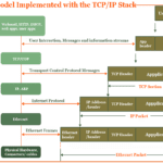
The Transmission Control Protocol/Internet protocol is a group of protocols developed by DARPA. These are the actual set of protocols used to implement the OSI model. TCP/IP is designed so that every computer, device or node in a network has a unique (IP) address. Apart from this, over 60,000 Ports are available for connections between IP addresses to send/receive data. The IP address serves to identify the device, while the port number distinguishes specific connections between the devices.